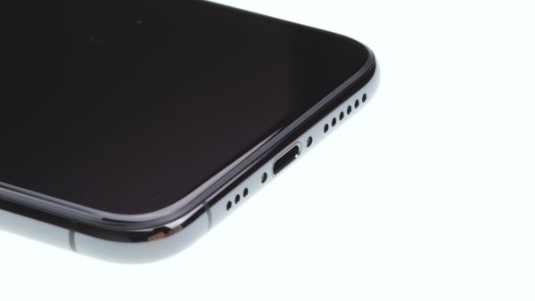
Your iPhone won’t charge, or the microphone isn’t working
Does your iPhone Xs not charge properly or does your PC not recognize your iPhone when you plug it in? By replacing the lightning connector, you can fix this problem. We'll show you how to do this in this repair guide.
For each step there is a small video sequence that shows you exactly how to proceed with the repair. The videos can always be started via the play button on the right corner in the first picture at each step.
Before repairing your iPhone, check if it's a software error by resetting your iPhone to factory defaults. Make a backup of your iPhone before repairing it.
Be particularly careful when loosening the front camera and FaceID unit and the earpiece, as these cannot be replaced without losing the FaceID function.
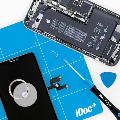
Required tools
-
Heat gun
Heat gun
You can use a heat gun to heat parts that are glued on so they’re easier to remove. In most cases, you can also use a hairdryer.
from €15.99 on Amazon -
iFlex Opening Tool
iFlex Opening Tool
Opening your smartphone can be a very delicate operation, especially if the glue is very persistent. The blade of the flexible but sturdy iFlex measures just 0.15 mm, so it fits in even the smallest gaps, such as between the screen and the frame. The practical iFlex is made of stainless steel and sits comfortably in the hand. This makes it the perfect assistant for every smartphone repair.
from €10.95 on Amazon -
For storing screws
For storing screws
We recommend storing your screws so you don’t mix up the various screws and small parts.
from €10.99 on Amazon -
Tweezers
Tweezers
We recommend using tweezers to remove screws and various small parts from your device.
on Amazon -
Pick Set
Pick Set
You need a flat but stable tool such as a pick to pry out parts that are glued in place.
from €14.99 on Amazon -
Plastic prying tool
Plastic prying tool
You need a flat plastic prying tool to disconnect the various plugs and connectors.
from €14.99 on Amazon -
Pentalobe PL1 screwdriver
You need the right screwdriver for removing pentalobe PL1 screws.
on Amazon -
Phillips PH00 screwdriver
You need the right screwdriver for removing PH00 screws.
from €10.84 on Amazon -
Phillips screwdriver with centering pin
Phillips screwdriver with practical centering pin for logic board screws.
on Amazon - Y-type Y000 screwdriver
Required replacement part
- iPhone Xs Lightning Connector Gray
Steps
29 Steps
Getting started with the repair of your iPhone Xs
If you get stuck or have questions, you can post a comment. We’d be happy to help.
-
Switching off your device
- Turn your iPhone off completely to avoid damaging it during the repair. Press and hold the Standby button and one of the two volume keys for three seconds, until the "Power off" slider appears.
- Swipe the slider from left to right. Now your iPhone will shut down completely, which can take about ten seconds.
-
Removing the back cover screws
- 2 × 6,8 mm Pentalobe
You need a pentalobe screwdriver (PL1) to open the iPhone Xs.
- Remove the two pentalobe screws at the bottom edge of the back cover. They’re to the right and left of the Lightning connector. Put the screws in the same box of your magnetic pad.
- Put your iPhone Xs on a soft, clean surface to avoid scratching the back.
-
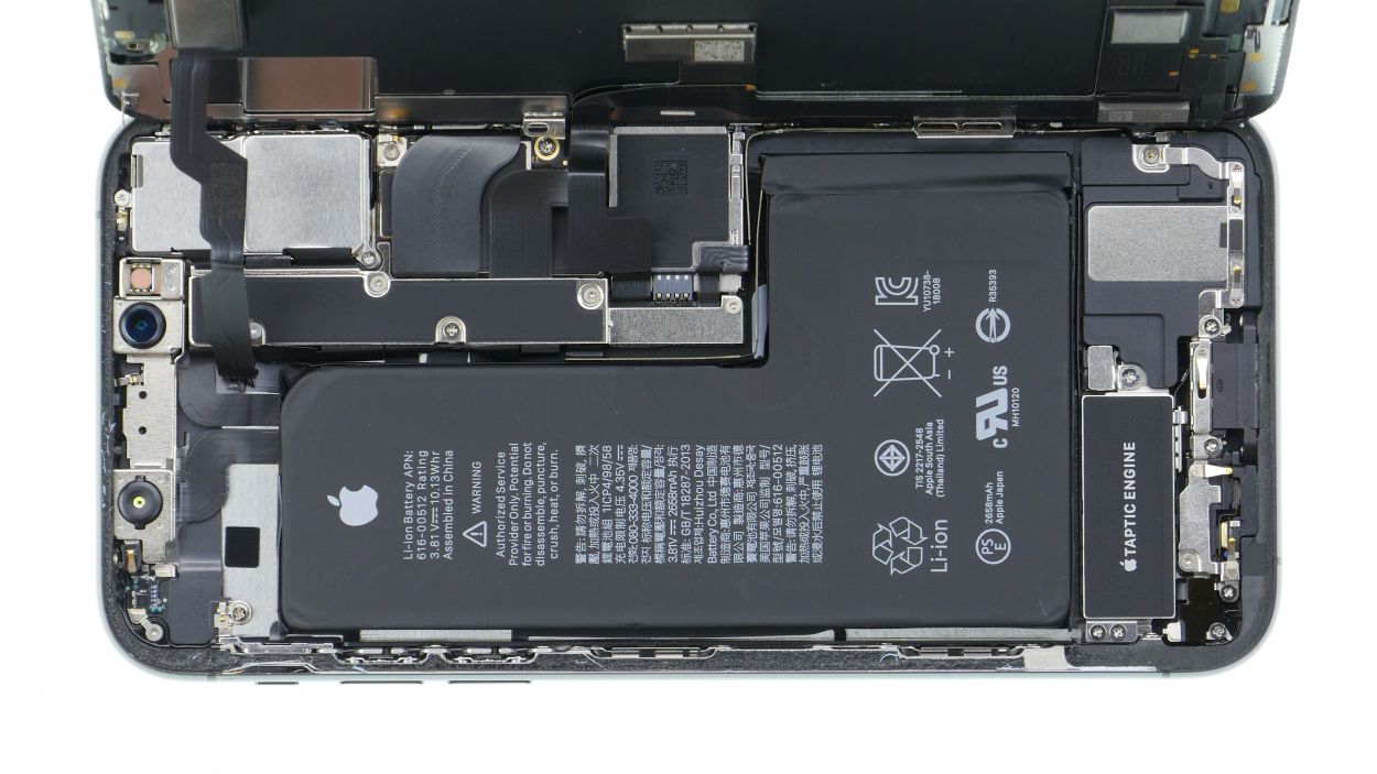
Removing the display
- To lift the front panel, you need a suction cup, a hard plastic pick and a heat gun. If the screen is severely cracked, cover all of it with packing tape before you continue.
- The screen is glued to the frame. Use a heat gun to heat the outer edges of the display to about 60°C (140°F).
- Place the suction cup over the Home button (if possible) or next to it. While lifting the screen with the suction cup, insert the hard plastic pick between the steel frame and the display frame and press down the steel frame.
If you can't get a plectrum into the gap, you can use an iFlex. But change to a hard plastic plectrum as soon as possible to avoid scratches on the frame.
- Because the display’s glued on all sides, you have to slide the pick all around the iPhone between the steelframe and the display frame. Don’t stick the pick in too far on the side where the Sleep/Wake button is because that could damage the display flex cables.
- Now use the pick to push up the display so the tabs disengage from the steel frame. Then you can fold the display over to the side. Rest the display on a stable object to avoid straining the sensitive flex cables.
Heat the outer edge of the frame several times if necessary.
-
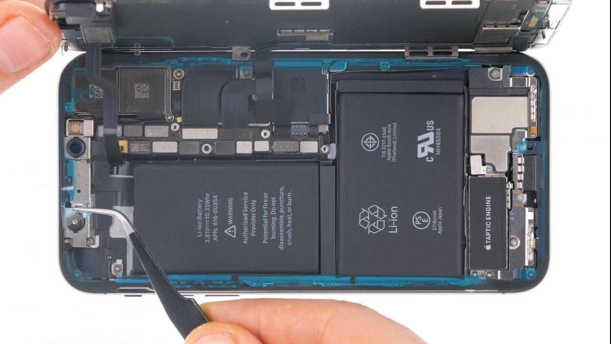
Disconnecting the battery
- 1 × 1,2 mm Y-Type
- 3 × 1,0 mm Y-Type
- 1 × 3,7 mm Phillips
- Battery Connector
Before starting the repair, disconnect the battery contact to prevent short circuits and avoid accidentally turning on your device during the repair.
- Use a Y-Type and Phillips screwdriver (Y000/PH00) to remove the screws. Then take off the bracket plate. Put all the parts in the same box of your magnetic pad.
- Now very carefully pry off the battery contact by inserting a spudger under the connector.
Note that the screws have different lengths
Apple introduced Y-Type screws with the iPhone 7. They are often wrongly called Tri-Point or Tri-Wing. Use a matching Y-Type screwdriver for these screws so you don't strip the screw heads.
-
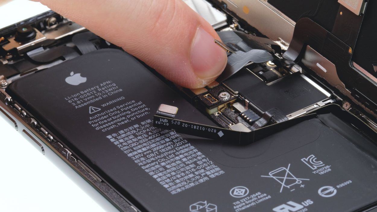
Disconnecting the display
- Display Connector
- Earpiece connector
- The display unit is connected by three flexible cables.
- Use a spudger to separate the connectors for the display and the earpiece one by one. Be very careful when prying off the connectors using the spudger to prevent damaging anything.
- The flex cable of the earpiece is still slightly glued to the cable underneath. Loosen it by carefully pulling it off. Use hot air to help yourself if the adhesive doesn't come off.
- If all connectors are off, you can remove the display. There may still be glue residue on the frame and display.
-
Removing the lower bracket plates
- 1 × 1,7 mm Phillips
- 1 × 1,6 mm Phillips
- 2 × 1,2 mm Phillips
- 1 × 1,0 mm Y-Type
- Remove the Phillips and Y-Type screws from the two brackets. The screws have different lengths. Place them on your magnet mat so that you can reassign them later.
- Then remove the two metal brackets. Both can be easily glued on.
-
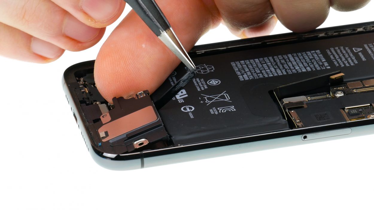
Removing the speaker
- 1 × 1,7 mm Phillips
- Speaker connector
- Loosen the single screw of the cover plate over the connector of the flex cable leading to the speaker.
- Then remove the cover plate.
- Then disconnect the connector of the flex cable and lift it up.
- Now you can lift out the speaker together with the flex cable. First lift the loudspeaker a little and loosen the rubber strip at the upper edge.
- Then pull the speaker all the way out.
The loudspeaker is strongly glued to the frame. To reinstall, remove any excess adhesive and make sure the adhesive is flush.
-
Removing the Taptic Engine
-
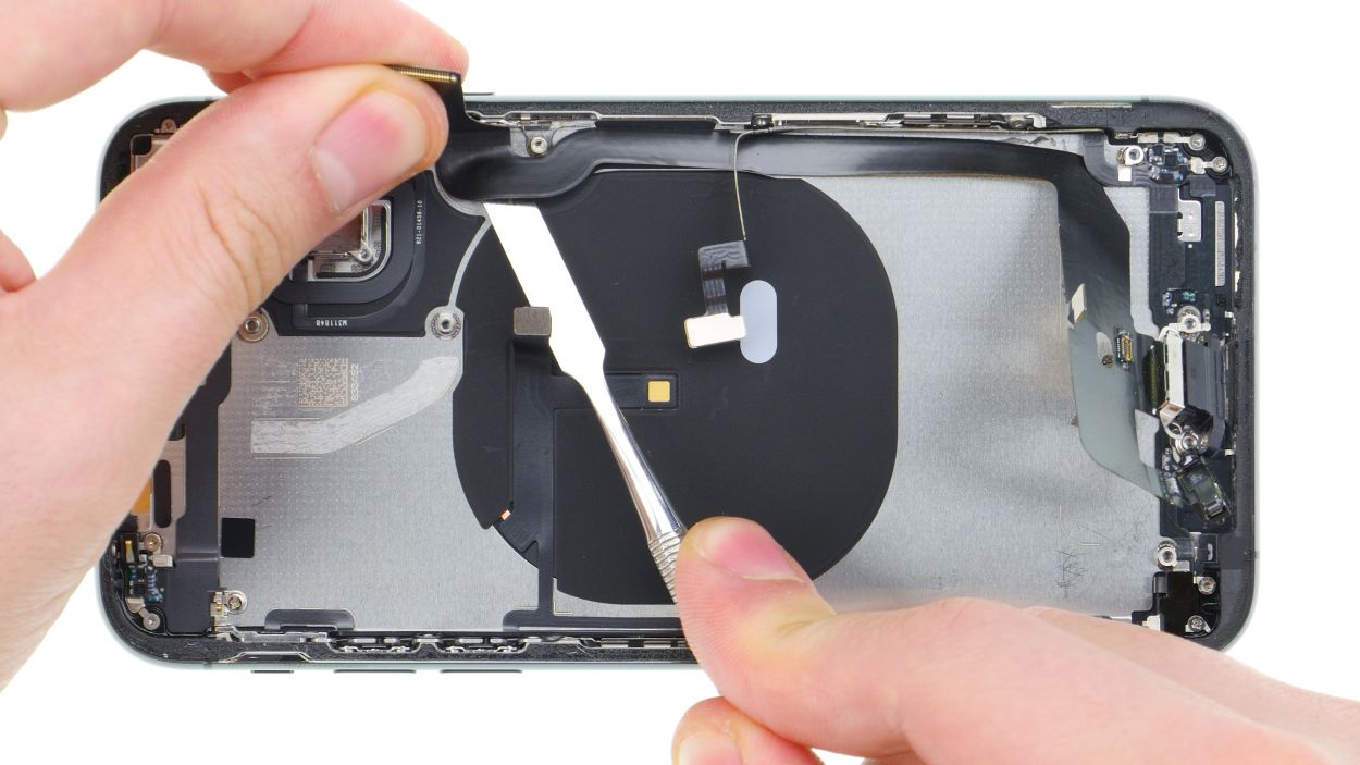
Removing the battery
The battery is glued to the case with four adhesive strips. The adhesive strips have tabs to pull them out. Three tabs are glued to the bottom edge and one strip to the top edge of the battery.
- Use tweezers or a spatula to peel off the black tabs. Underneath are the white adhesive strips.
- Now pull out the adhesive strips very slowly. Keep the strips as flat as possible at the level of the iPhone.
- You can pull out the adhesive strips with your fingers or wrap them on the tweezers. How to do this is best seen in the video (play button in the upper right corner of the first picture).
- Once all the adhesive strips are off, you can remove the battery.
Make sure not to damage any flex cables at the bottom and top edge of the battery.
If one of the adhesive strips tears, you have to pry out the battery carefully using a wide Spudger. Try to bend the battery as little as possible.
Firmly hold the battery and iPhone while pulling out the last adhesive strip to prevent the battery from falling out of the device.
-
Removing the camera
- 1 × 1,3 mm Y-Type
- 1 × 1,8 mm Phillips
- Camera Connector
- Loosen the two screws securing the iSight camera cover plate.
- Lift up and remove the cover plate. It is hooked into the side of the standby button.
- Then separate the two connectors of the double camera with a spudger. Carefully lever and take care not to damage the pins on the logic board.
- Lever out the camera with the Spudger and remove it.
-
Removing the front-facing camera and FaceID unit
- FaceTime camera
- IR camera
- Dot projector
The assembly with the front camera and the FaceID components (IR camera and dot projector) is connected to the logicboard with three connectors.
Be particularly careful with this step, as damage can lead to the loss of the FaceID function.
- Carefully disconnect all three connectors with the Spudger.
- Then heat the slightly glued flex cables and pull them out of the backcover.
- The whole front-facing camera unit is hooked in on both sides. Lever it a little and then take it out. Make sure that no more cables are stuck.
-
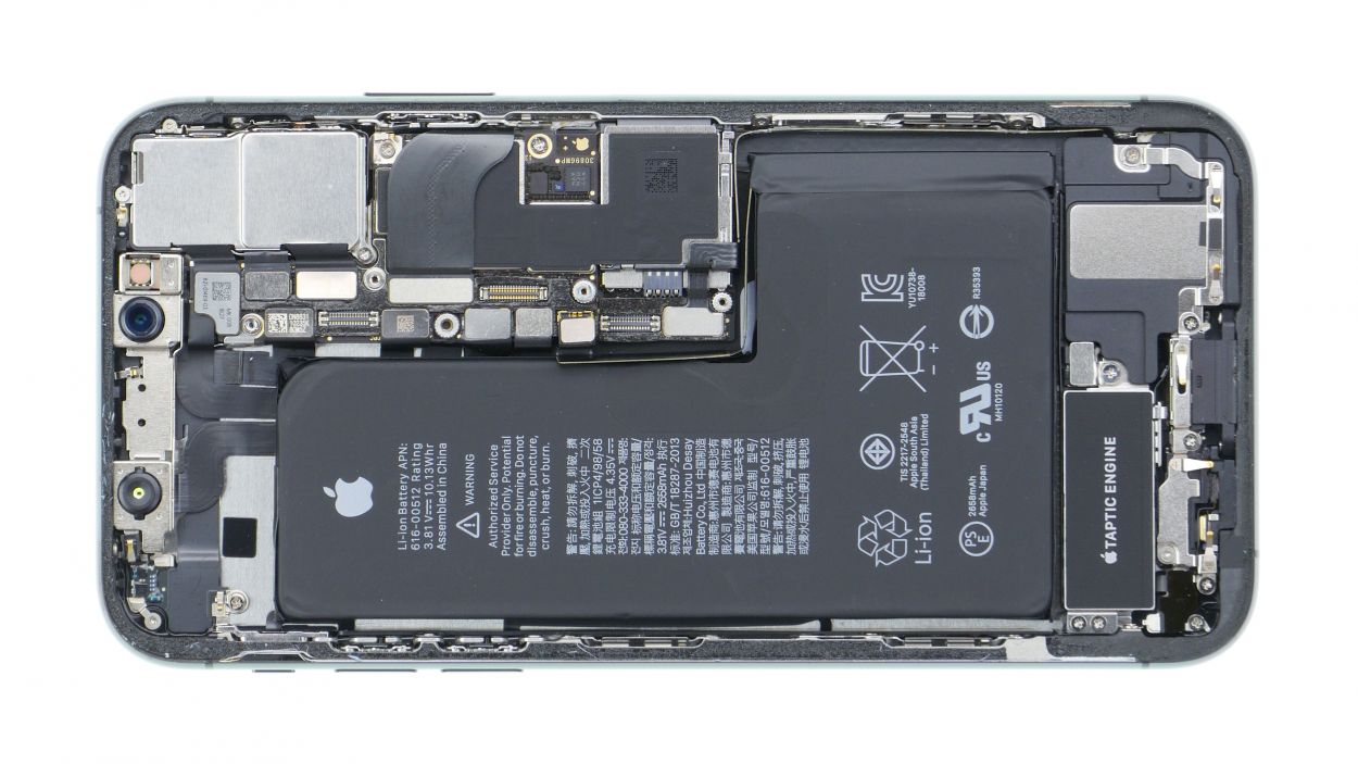
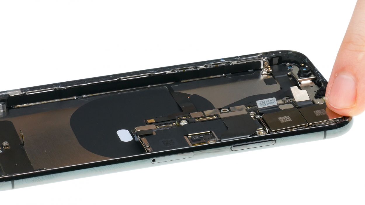
Removing the logic board
- 1 × 3,6 mm Standoff
- Connectors
- 1 × 3,1 mm Phillips
- 1 × 2,3 mm Phillips
- Connectors
Two of the contacts on the logic board are still under a cover plate. For the screw with internal thread, also called Standoff screw, you can use a thin slotted screwdriver. There are also special screwdrivers with a cross profile and a pin in the middle.
- Remove the Standoff screw and loosen the cover. The bracket is hooked into one side.
- Loosen the two contacts carefully with a spudger.
The contacts are very firmly connected to the logic board and are not easily accessible. If you can't get any further with a Spudger, you can also lever very carefully with tweezers or another thin tool.
- Then disconnect all other contacts from the logic board. They connect for example the charging socket, the flashlight and the volume keys.
- Then unlock the SIM card holder and take it out.
- Loosen the screws of the motherboard.
- Then carefully bend all flex cables to the side and remove the logic board.
-
Removing the barometric vent
-
Removing the Lightning Connector
- 1 × 1,1 mm Y-Type
- 1 × 2,5 mm Standoff
- 2 × 3,0 mm Phillips
The flex cable of the charging socket is glued to the back cover and secured with several screws. To get to one of the lower screws you first have to remove a small piece of plastic with a microphone from the frame.
- Carefully lever until you can bend the part a little to the side.
- Loosen all screws of the Lightning Connector. The two long screws that lead down are a bit more difficult to loosen.
Heat the entire flex cable with the heat gun to loosen the glue more easily.
- Use the steel spatula to slide under the cable and gradually remove it from the back cover. Be careful not to damage it with a sharp edge of your tool.
- Lever the charging jack out of its guide and then loosen the rest of the cable. Heat several times to make the glue easier to remove.
- When everything is loosened, you can remove the Lightning Flex cable.
-
Installing the lightning connector
- 1 × 1,1 mm Y-Type
- 1 × 2,5mm Standoff
- 2 × 3,0 mm Philllips
- Position the Lightning Connector in the iPhone and slide the charging socket into its opening at the bottom.
- Lead the flexible cable under the other and then along the edge.
- Screw the Lightning Connector on and insert the screw of the other flexible cable on the side.
- Then press the microphone unit against the lower edge of the housing. Insert the small nose into the opening in the frame and the microphone will be seated correctly.
-
Installing the barometric cover
-
Installing the logic board
- 1 × 3,1 mm Phillips
- 1 × 2,3 mm Phillips
- 1 × 3,6 mm Standoff
- Connectors
- Make sure that all flex cables are lying flat in the backcover and then insert the logic board. Bend all cables a bit to the side so that you don't trap any of them under the logic board.
- Secure the logic board by inserting the screws.
- Insert the SIM card holder. You shouldn't feel any strong resistance, otherwise the Logicboard might not fit properly.
- Then connect all connectors. Take your time and proceed carefully. Position the connectors above their positions on the logic board and press carefully. The contacts should engage slightly. Don't slide the plugs back and forth and try not to push them tight with force. Use a spudger for the small plugs at the top to push them down.
- Hook the cover plate of the two contacts on one side and screw it down.
-
Installing the front-facing camera and FaceID unit
- FaceTime camera
- IR camera
- Dot projector
- Now place the assembly with FaceTime camera and infrared sensor in the device. Hook the metal brackets on both sides under until the whole module sits correctly.
- Press the flex cables in the backcover a little bit in.
- Connect all three connectors on the logic board. If a flex cable isn't sitting properly flush, correct it again.
-
Inserting the camera
- 1 × 1,3 mm Y-Type
- 1 × 1,8 mm Phillips
Make sure that there is no dust or fingerprints on the camera lenses and on the inside of the camera cover.
- Place the iSight camera back in its place and press it down.
- Plug in the connectors of the two cameras.
- Put the bracket plate in its place. Make sure it hooks into the side of the standby button.
- Screw in the bracket plate using the two screws.
-
Preparing the battery
Place the adhesive strips with protective films attached in the device to make sure that they point in the right direction.
- Remove the large blue protective film and stick the adhesive strips to the bottom of the battery. Make sure they are straight.
- Remove the large pink protective film from the adhesive strips.
- Fold the tabs on the sides and press them against the battery.
When attaching the adhesive strips, leave enough space on both sides to fold over the tabs.
It may be that your replacement battery has already attached adhesive strips. Then of course this step is skipped.
-
Inserting the battery
- Place the battery back in the rear case and press it in to make it stick.
Leave some space at all edges of the battery to other components and the frame so that the battery is not jammed in the frame.
-
Installing the Taptic Engine
- 2 × 1,8 mm Phillips
- Taptic Engine Connector
- Put the Taptic Engine back between the battery and the Lightning connector. Make sure the screw holes of the Taptic Engine sit correctly.
- Connect the Taptic Engine’s connector.
Make sure it sits correctly and press it a little into place with a tool if necessary.
- Fasten the Taptic Engine with the phillips screws.
When you've replaced the Taptic Engine, take over the rubber strip.
-
Inserting the speaker
- 1 × 1,7 mm Phillips
- Speaker connector
- Put the speaker back in place and push it toward the bottom so that it sticks into place.
- Be careful not to pinch the rubber strip under the speaker.
- Then connect the speaker's connector and secure the cover plate with the single screw.
Make sure that the connector is seated correctly again.
-
Installing the lower bracket plates
-
Attaching a new frame sticker (optional)
In the pictures you can see iPhone X. The iPhone Xs is built in the same way and is re-glued in the same way.
- To make sure that the new frame sticker will really stick, remove all glue residue and dirt from the metal frame.
- Remove the first protective film layer of the frame sticker.
- Position the frame sticker carefully on one edge of the frame and attach it gradually. Make sure the frame sticker is positioned evenly and press it on. You can use the plastic spudger to press the adhesive on.
- Remove the next large protective film.
- You can leave the small protective films on for now and remove them when you've connected the display and attached the bracket plates. This prevents anything from sticking to the frame sticker before you install it. But you can also remove the films right away.
Please make sure the frame sticker is positioned correctly. Each corner has a different shape, which you can use for orientation.An iPhone repaired with a frame sticker will be protected against dust and spray water, but it will not be 100% waterproof!
-
Connecting the display
- Display Connector
- Earpiece Connector
- Place the display unit on the edge of the frame and rest it against a stable object, in order not to overstretch the sensitive flex cables. Make sure your device doesn't slide away.
- Connect the two display connectors.
- You might need to press down the lower of the two connectors with a spudger to make it sit properly. Make sure the connectors attach properly. Don't slip and bend the socket contacts on the logic board.
- Use tweezers to position the earpiece connector over its socket on the logic board.
- Carefully press to attach the connector to its socket.
-
Connecting the battery
-
Installing the display
-
Fastening the back cover screws
The right tools for your repair
Bewerte unsere Anleitung
Hat dir unsere Anleitung weitergeholfen? Wir sind auf deine Beurteilung gespannt.
Submit ratingBewertung gesendet
Similar guides
You might also be interested in these guides.
You might be interested in